

multidisciplinary life science building

Visualization - SevenHundred
introduction
Location: San Diego, CA, USA
Phases Involved: Pre-Design - Schematic Design - Design Development - Construction Documentation
Role & Responsibility: Exterior façade design and construction documentation
An ambitious expansion in support of higher education biomedical research, the project aimed to redevelop an existing parking lot with a state-of-the-art 200,000 sqft concrete 6-story laboratory and undergraduate teaching facility. The building would support the client’s desire for a maximally efficient and highly flexible research facility that would enhance connectivity to major pedestrian and vehicular pathways on the rest of campus. This would be achieved by conceptualizing the building with a “side-core” layout and gathering all MEP and utility conduits towards one side of the building, which would create a completely open floor plan with the ability to be reconfigured in the future. The articulation of the building’s massing would create exterior terraces on every level, taking advantage of the region’s famous weather and emphasizing visual connection to all parts of the campus.
My responsibilities included conceptual site and massing diagrams during the pre-design phase, physical model mock ups, initial BIM digital construction and layout, façade system BIM family development, and construction documentation for all exterior design elements.
Existing Site Constraints
Axonometric site context diagram
The site’s proximity to major pedestrian and vehicular thoroughfares, a large parking garage to the west, and certain underground utilities that formed the perimeter of the site provide the major constraints for the initial massing studies.
Once the maximum viable ground level footprint was established, further studies to hit the target FAR without triggering “high rise” designation found that additional square footage could be gained on each of the upper levels by strategically overhanging the ground floor and expanding the floorplates. Though only to a point. Clear distance had to be maintained from the existing buildings to the east, west, and south. To the south a maximum addition of 26 feet, and 10 additional feet to the east.

Site Constraints Axon
Site Constraints Plan
Site Constraints Site Section
massing
With the site context boundaries and maximal achievable FAR established, massing articulation studies formulated a series of architectonic moves, each in the service of one of the desired project objectives. These initial moves would be dialed in as the project progressed.

floor Plans

The general program distribution thus follows in the proceeding diagram:
Much of the utility and laboratory back of house facilities are located in the basement and lower levels of the building.
The ground level hosts all of the undergraduate teaching facilities and laboratories, easily accessible from the ground-level entries and siloed from the upper level research facilities by way of keycard access.
Levels 2-5 contain the main bulk of research facilities and researcher offices, all in an open floor plan made possible by shifting the bulk of utility conduits to the far west of the building in a “side-core” configuration.
Typical floor plans


light shelf
Floor Plan Organization
The “side-core” layout created a wide open floor plan, which could also be understood to be a deep floor plan. In order to reduce the need for artificial lighting and energy usage, the concept of interior and exterior light shelves was designed to bring natural sunlight as far into the floor plate as possible. The researcher offices would be arranged adjacent to the exterior curtain walls, their ceilings brought down low to preserve the clerestory windows while also serving as the interior light shelf.
Interior Light Shelf Diagram
This concept was validated with solar studies that investigated the difference in effective interior lighting such a design would provide. The studies also informed the most effective shape of the sunshade fins in relation to the site’s solar heat gain.
Interior Light Level Study
Sunshade Concept Diagram
Curtain Wall Panel Diagram
Elevations


Sectional Perspective
The following sectional perspective displays the three preceding concepts of “side-core”, conceptual massing, and light shelves in one cohesive representation.


Visualization - SevenHundred
Construction documentation
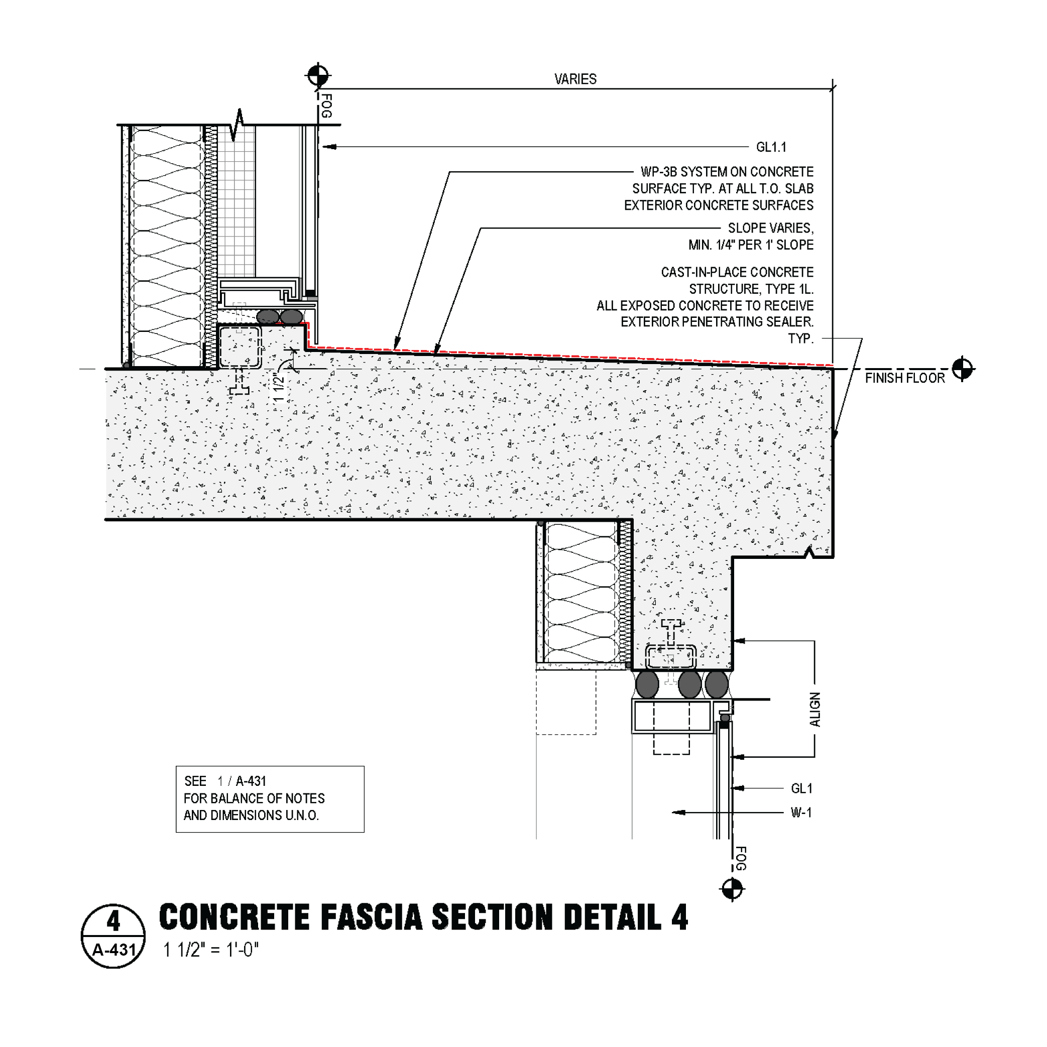
Over the course of the CD phase, I was tasked with all exterior curtainwall and facade to concrete adjoining conditions. The following represent examples of the construction documentation I was responsible for.
exterior elevations


Selected enlarged exterior details
Referenced details noted in red
Northern Main Entrance Views & Construction Details


Southern Trash Enclosure Elevation & Construction Details


Typical Exterior Terrace Details


typical enlarged exterior elevations & construction details
Referenced details noted in red


VIsualization - SevenHundred