LUSK CAMPUS FACADE
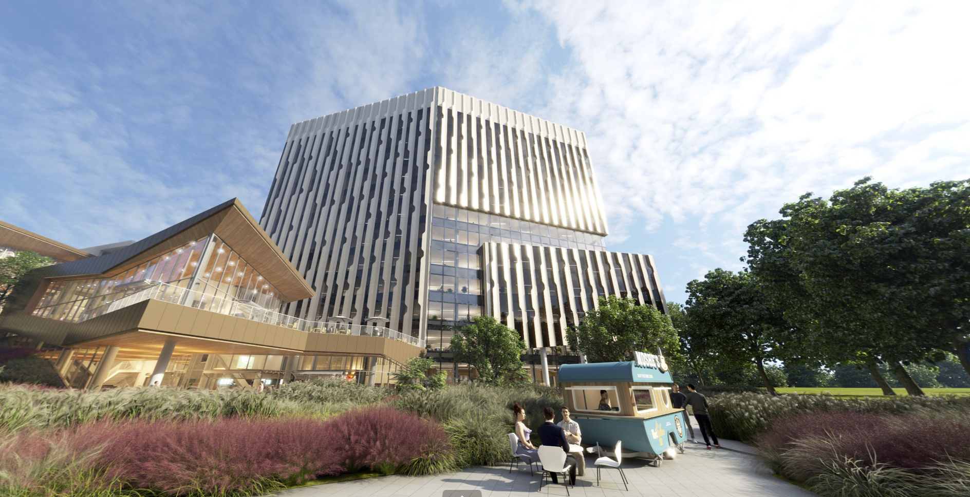
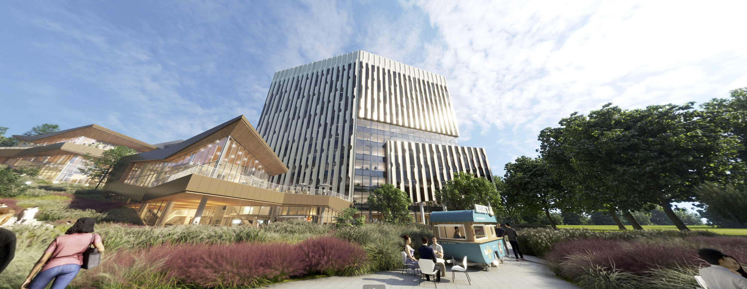
Visualization - SevenHundred
introduction
Location: San Diego, CA, USA
Latest Phase: Design Development
The project aimed to redevelop a 20.6 acre lot in San Diego into a state of the art science research campus to service the nation’s growing life sciences sector. Plans included the development of seven new ground-up steel construction office towers, two large amenity facilities, and three additional parking garages to accommodate the increase in site occupancy.
Completely aware of the impact the large mass nature of the new development would have, the client’s primary design brief was to connect the proposed campus facilities to the character of the site and context in order to integrate its form and mitigate its presence. My primary role during this project was to develop a comprehensive design character for the campus office buildings’ visual identity and explore form, proportions, and materials related to its execution.
Schematic Design
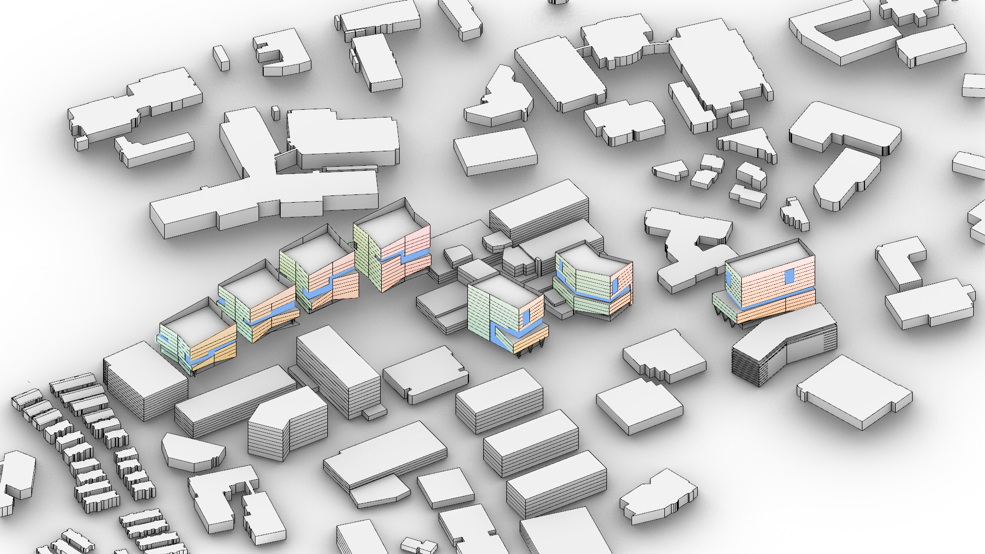
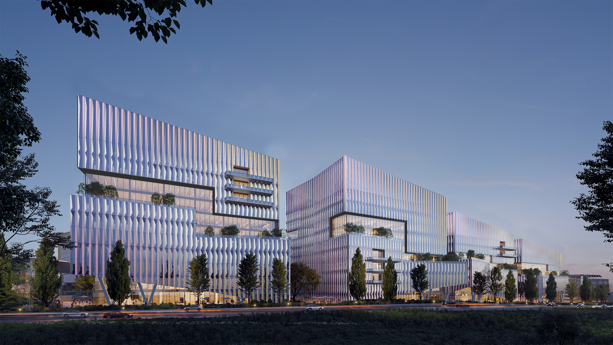
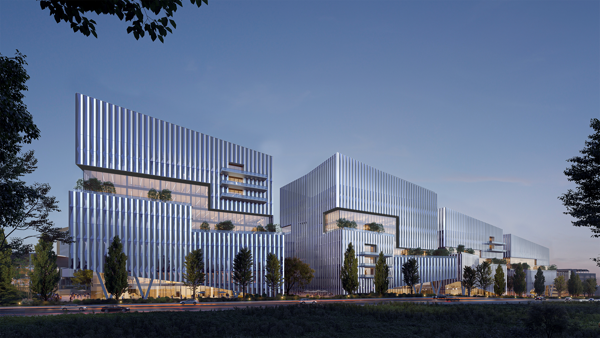

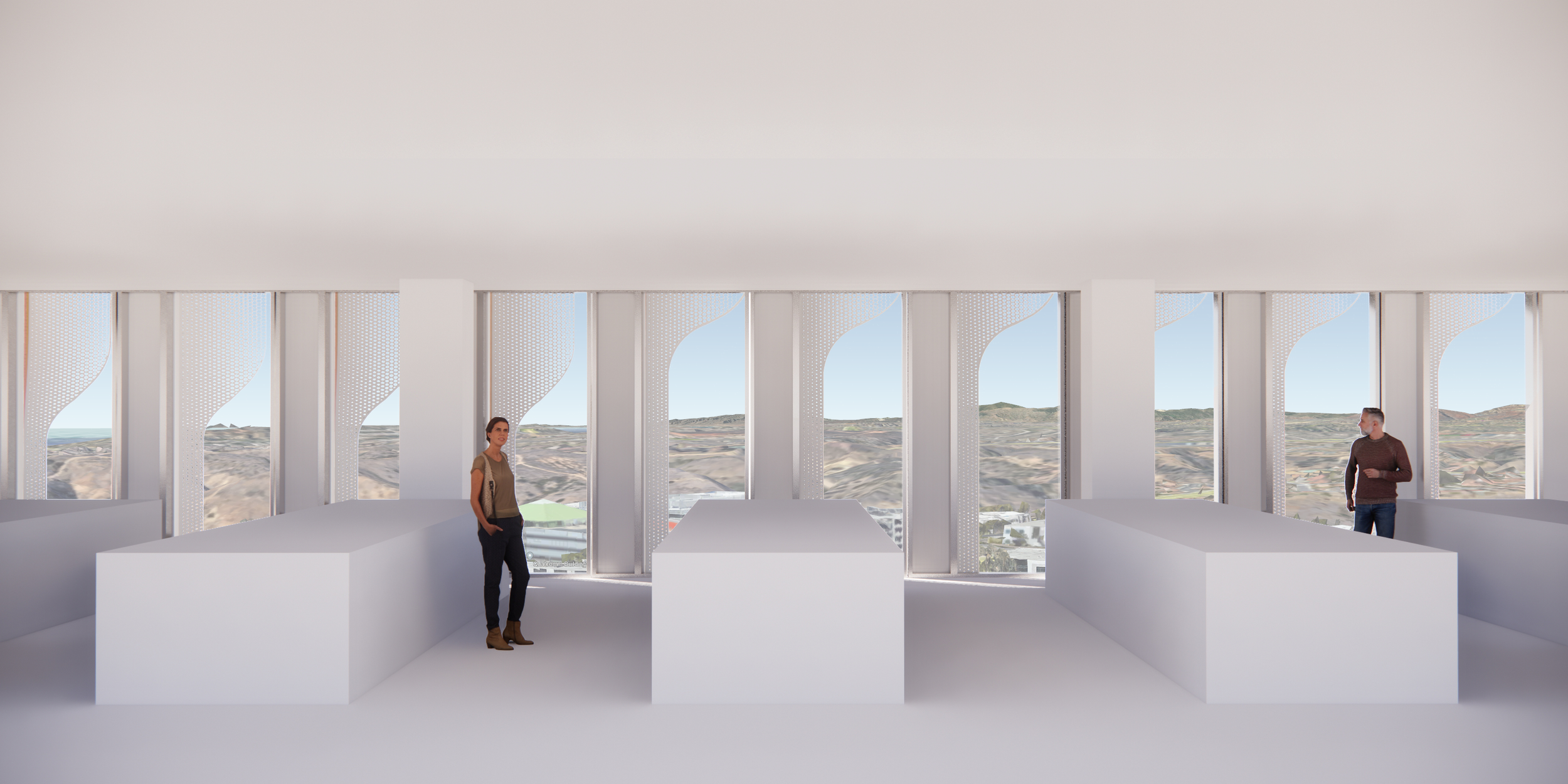
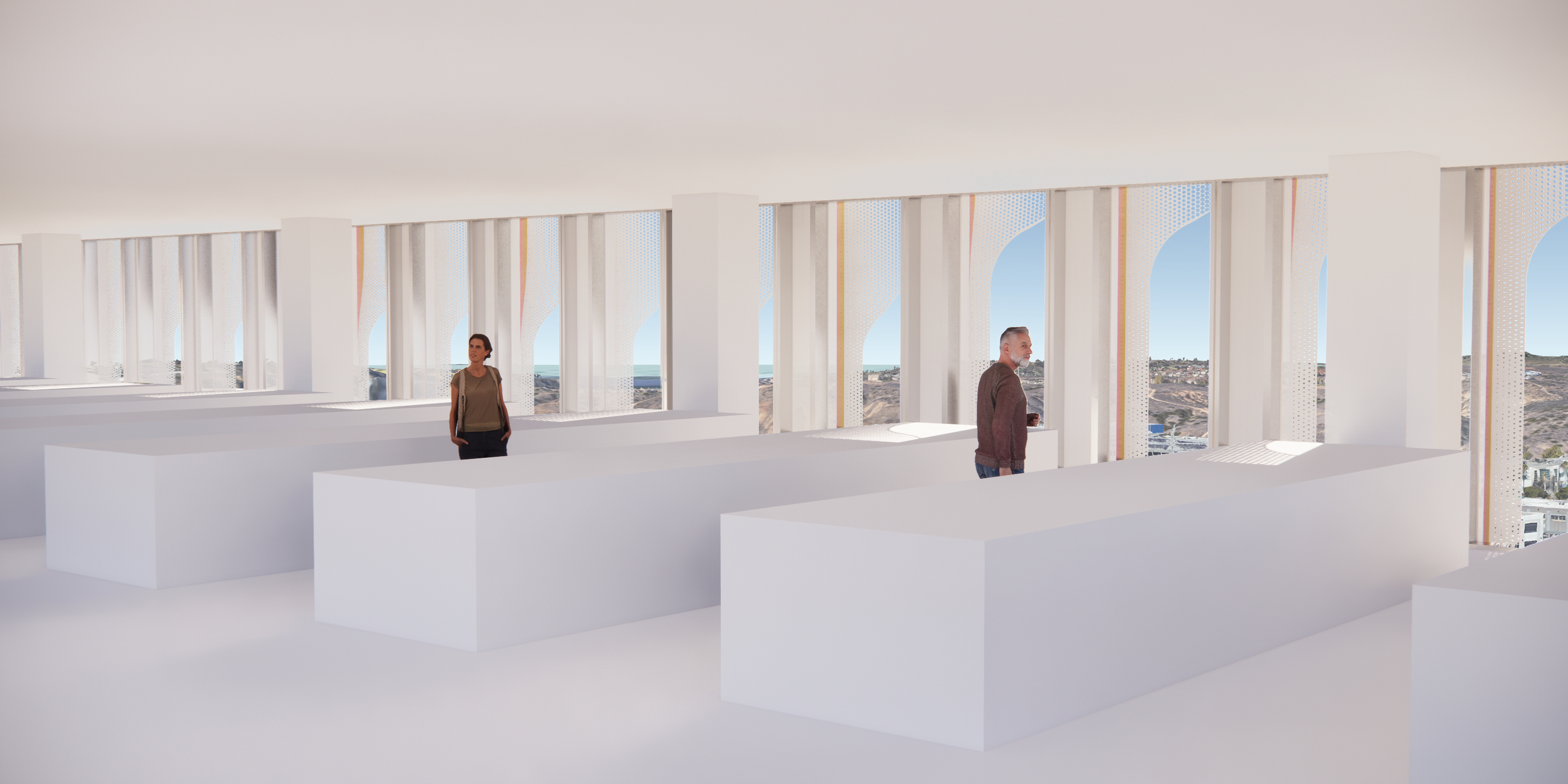
A design element unifying all campus buildings was a continuous “river” of clear unobstructed glazing as seen in the first image of the above gallery represented in light blue. Each building’s mass would be divided by this “river” connecting one building to the next, and would also serve as opportunities to articulate form to provide exterior balcony space.
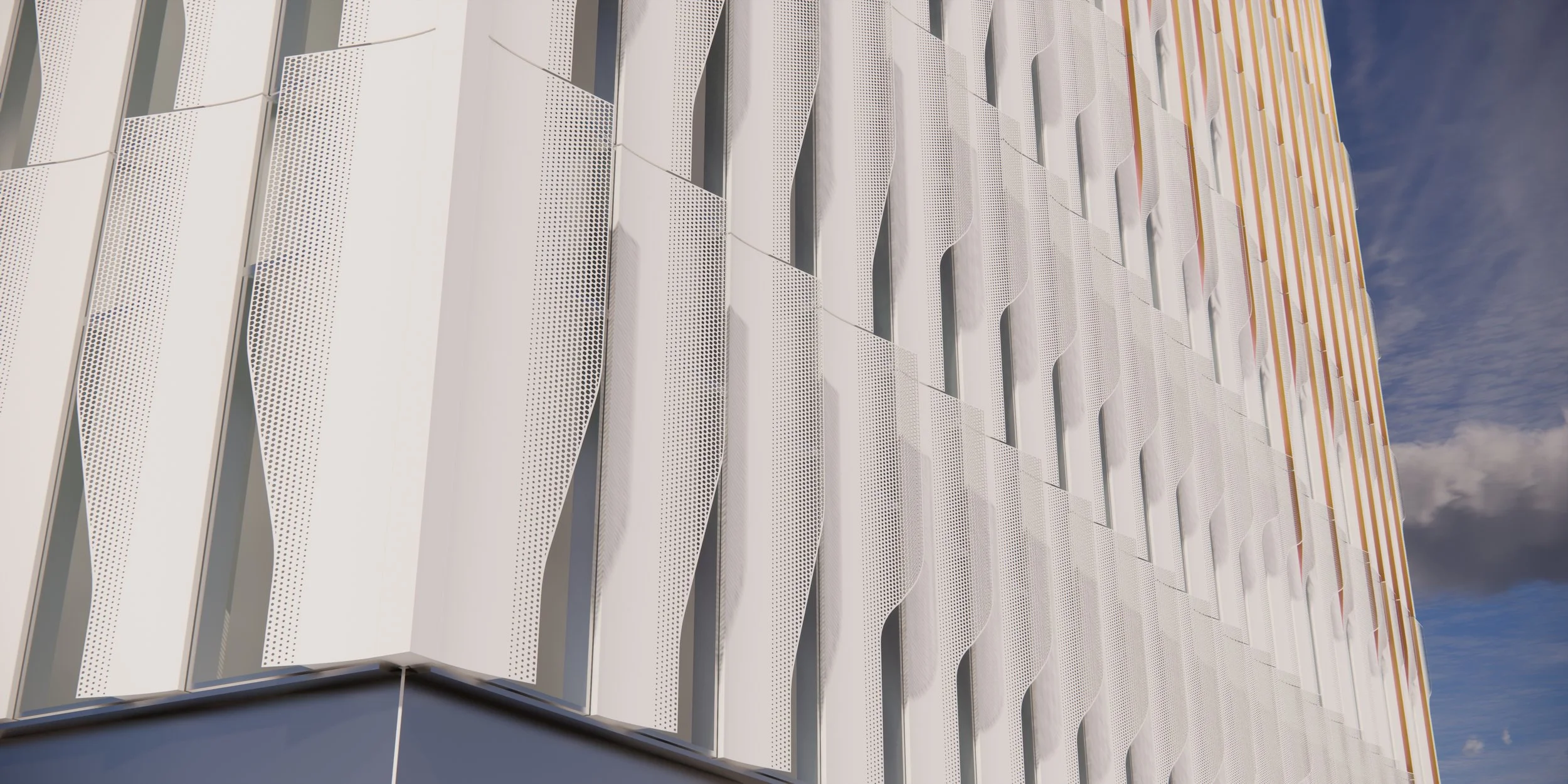
Initial schematic design explorations investigated a multitude of directions to characterize the facade adjacent to the “river”, including articulated spandrel panels, dichroic glazing, gradient frit treatment, etc. Ultimately a system of articulated spandrel panels and perforated sunshading elements was chosen, selectively applied towards areas with the most solar heat gain, while adjacent portions of the building facades would be treated with frit articulating a similar geometry to the sunshading fins.
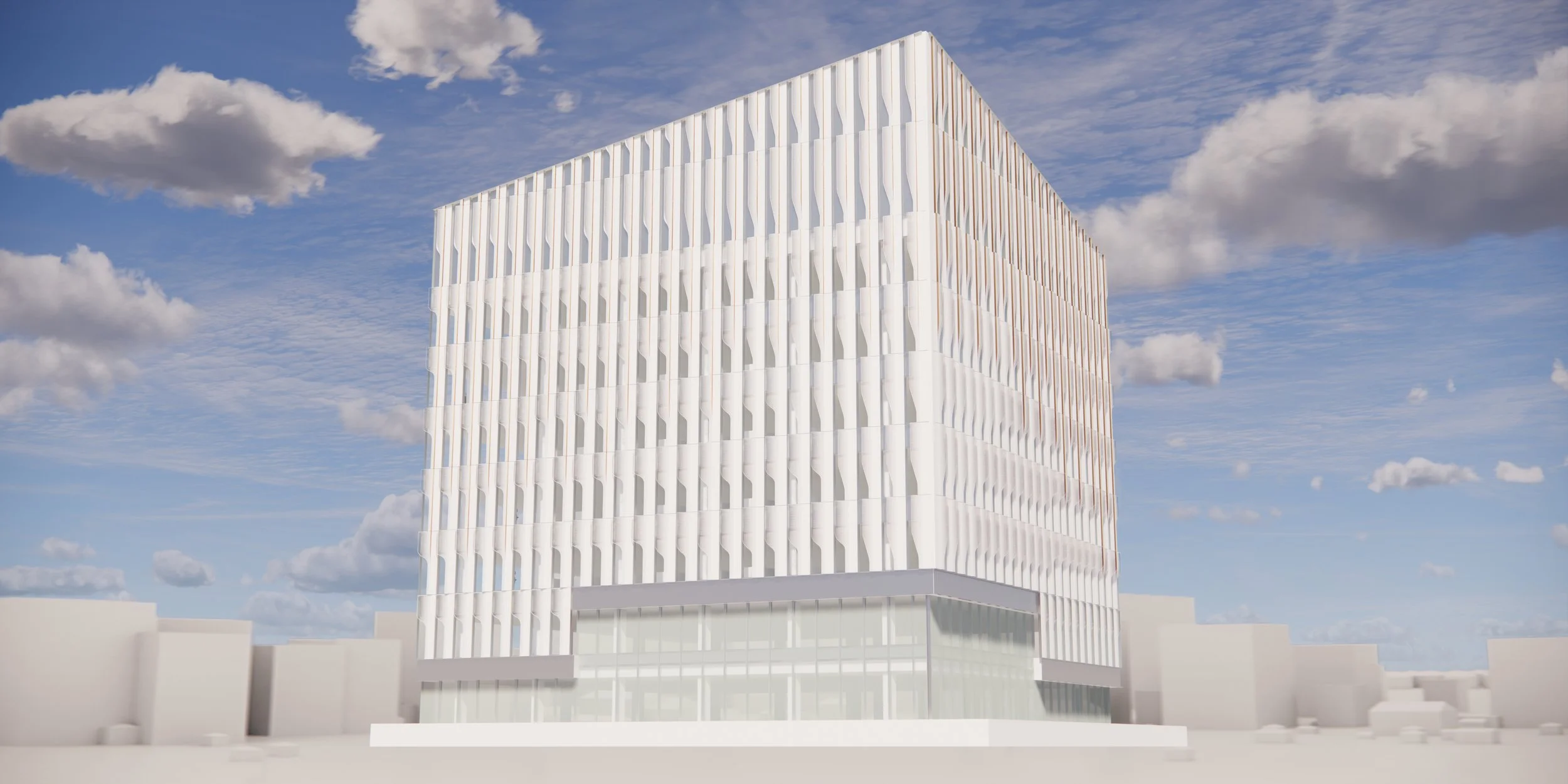
schematic design clay renders
fin articulation diagram
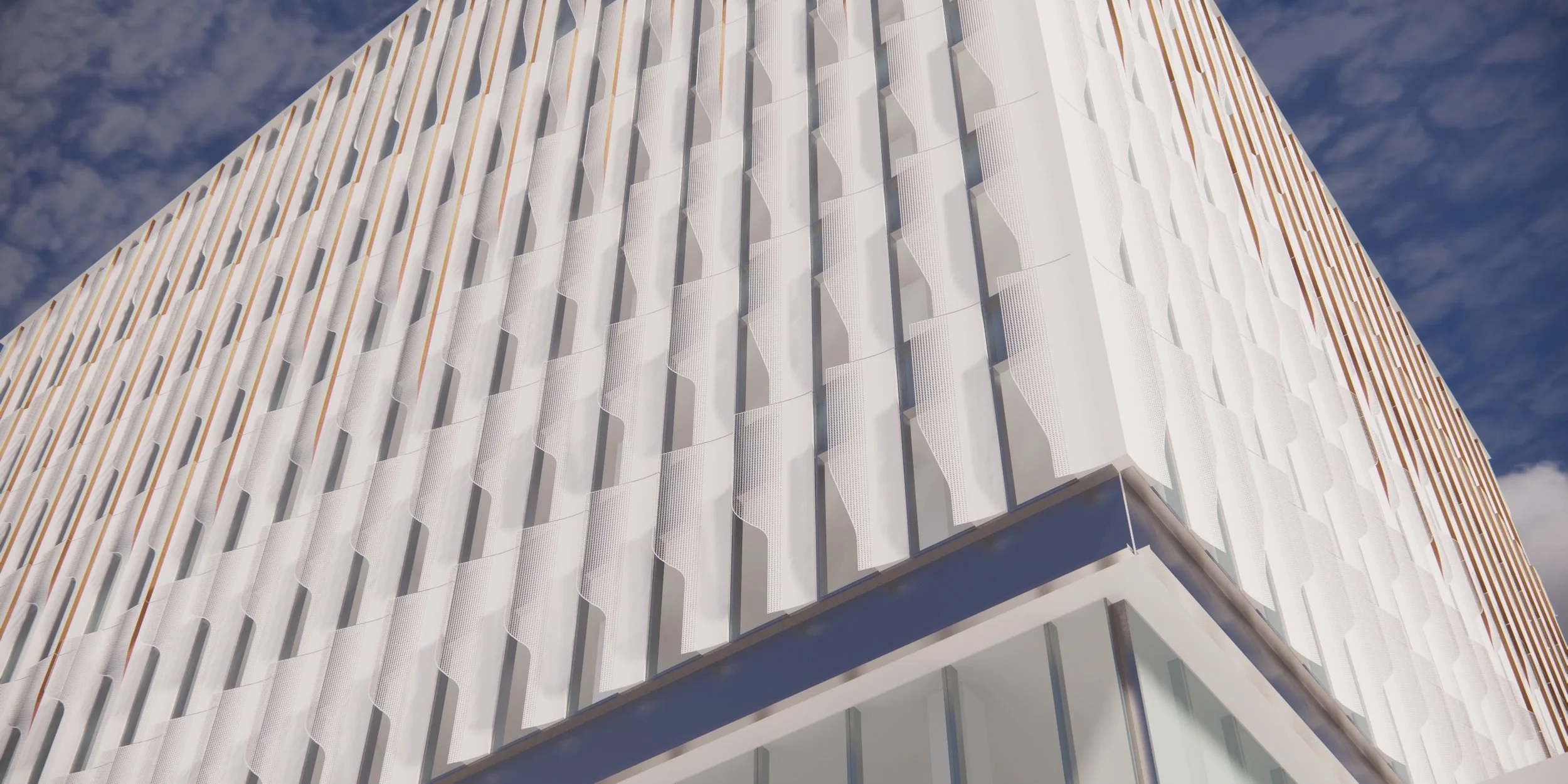
The first iterations of the sunshading element took inspiration from the soft wave of sails and wings, common sites along the region’s beaches, the perforated forms emerging from a curved aluminum spandrel panel. The three dimensional articulation of the sunshading also allowed for integration of dichroic elements along the side of the fin, creating a sense of ever shifting imagery as one would traverse the site.
frit studies
Frit studies explored the possibilities of articulating human scale perception from the interior of the building during occupancy. Fritted glazing would be a cost effective way of mitigating solar heat gain along facades that faced away from direct sunlight while also maintaining a unified character with the rest of the building’s facades.
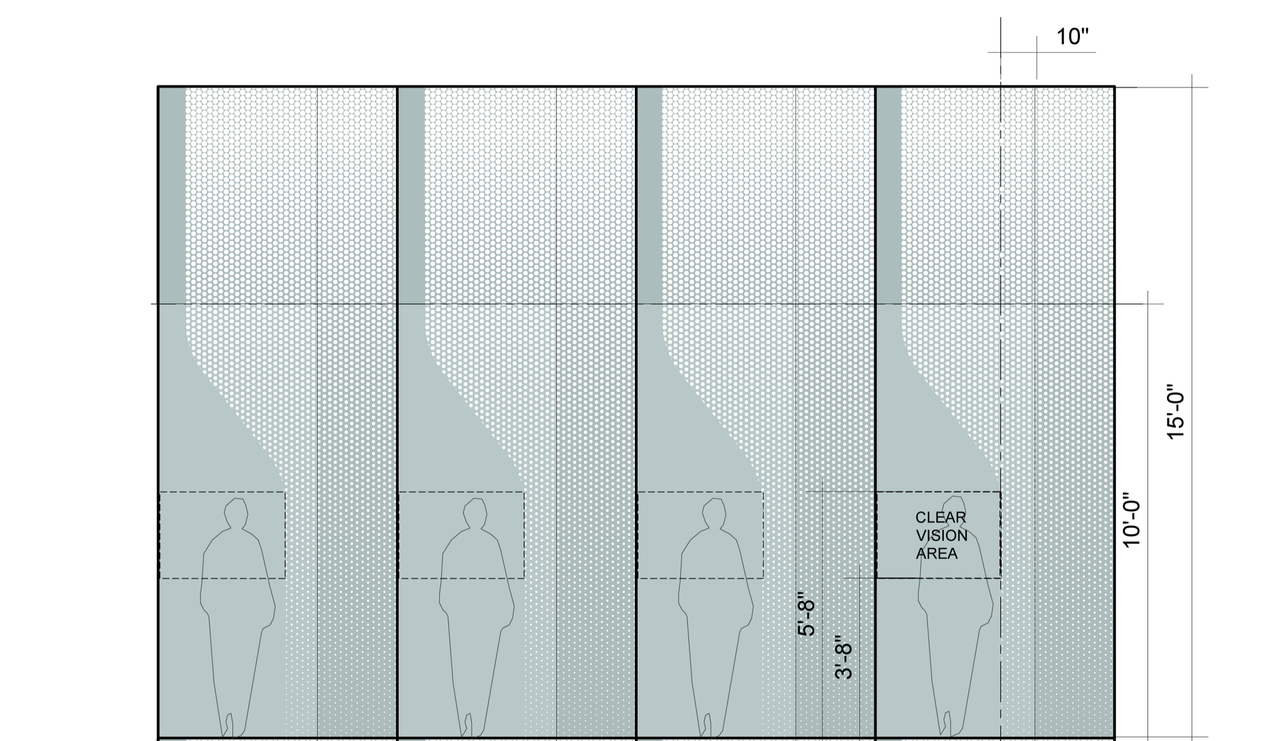
vertical connective modulation
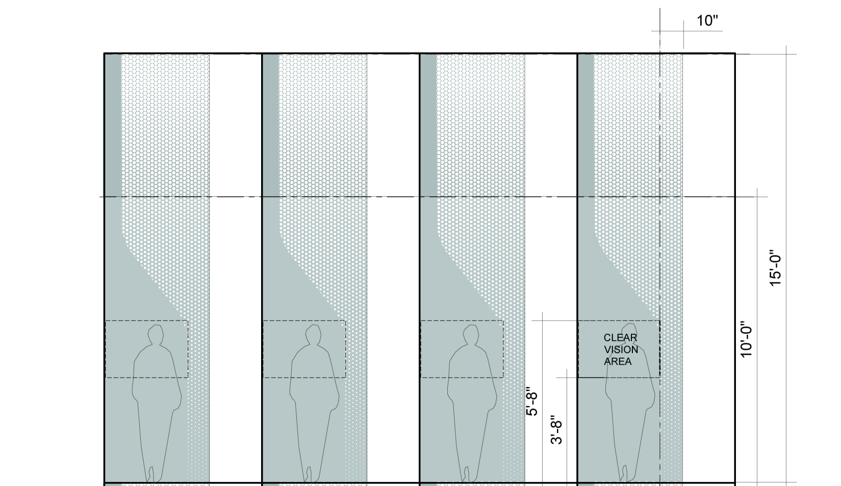
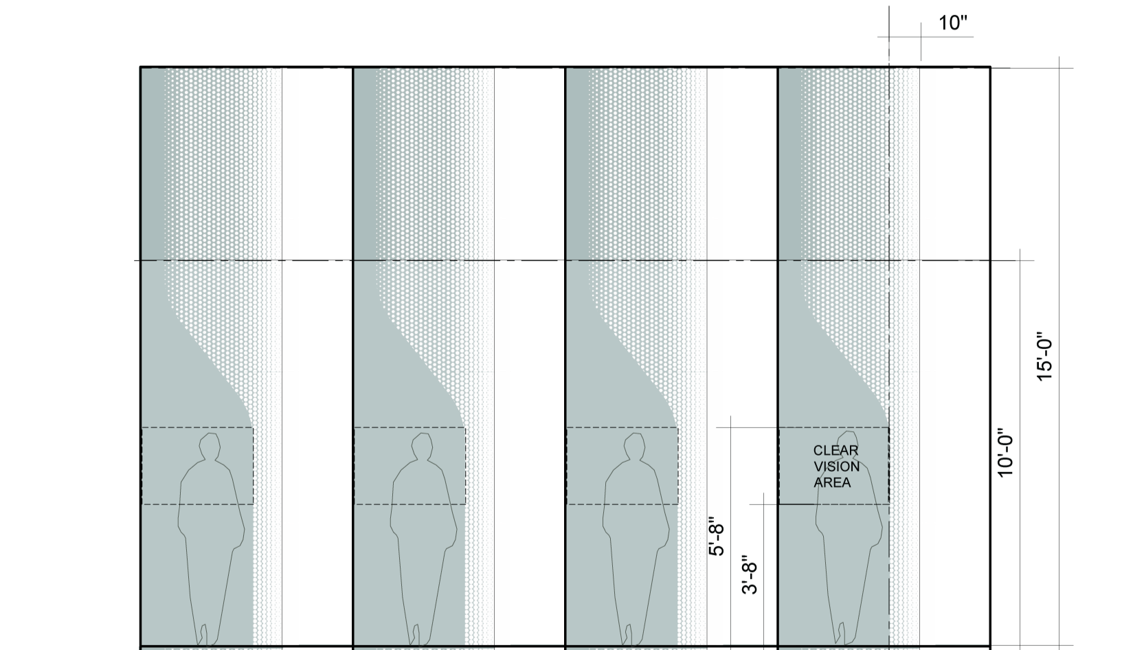
Further Schematic Design investigation uncovered a desire to unify the sunshading elements vertically, creating a continuous sense of motion between floor levels. To accomplish this, gradient frit and three different fin forms were developed as a first pass. The shapes were continuously informed by the requirement for a clear viewing zone between 3’-8” and 5’-8” from the finish floor as noted in the previous diagrams. but in order to connect to the forms, the fins and frit would resemble a notched form.


Design Development
As the scheme transitioned into Design Development, the need for simplification and a more sophisticated transition from sunshading fin to frit were of an increasing concern. The sunshading fins were thus simplified, eliminating three axis articulation and dichroic elements in favor of a simple angled fin emerging from the primary vertical spandrel panel.
Complex geometry was also eliminated, with fins and frit shapes reduced to a single notch typology and at a consistent angle and radius.
A persistent spandrel panel was also added to the frit typology as a unifying feature.
facade typologies
These façade elements were also organized into three different categories of typologies: Frit Only, Fin Only, and Transition (which combined elements of the two previous typologies). In this manner, each panel type could be tied to the panel above or below in a seamless manner. They could also be blended horizontally creating a smooth gradient from fin to frit and vice versa without visually abrupt breaks, creating variability in what would otherwise be a field condition.


fin to frit transition diagrams
The unwrapped elevation diagrams below display a range of possible distributions of the three façade typologies and their ability to introduce articulation, while also reducing cost by focusing the more expensive sunshade element where solar studies have dictated to be most crucial.
![barnes elevation unwrap [Converted]-08.jpg](https://images.squarespace-cdn.com/content/v1/55e0587ae4b0c1436c8f8c00/1757583332387-1WPR7K7H5UG031R4VPPA/barnes+elevation+unwrap+%5BConverted%5D-08.jpg)
![barnes elevation unwrap [Converted]-02.jpg](https://images.squarespace-cdn.com/content/v1/55e0587ae4b0c1436c8f8c00/1757583332462-072JEHUCVOBNGBCYDO0G/barnes+elevation+unwrap+%5BConverted%5D-02.jpg)
![barnes elevation unwrap [Converted]-03.jpg](https://images.squarespace-cdn.com/content/v1/55e0587ae4b0c1436c8f8c00/1757583338457-6O3RZEF9M7SB0Z54O4R0/barnes+elevation+unwrap+%5BConverted%5D-03.jpg)
![barnes elevation unwrap [Converted]-06.jpg](https://images.squarespace-cdn.com/content/v1/55e0587ae4b0c1436c8f8c00/1757583338614-N7BTTECO6KIOPALU26UA/barnes+elevation+unwrap+%5BConverted%5D-06.jpg)
![barnes elevation unwrap [Converted]-07.jpg](https://images.squarespace-cdn.com/content/v1/55e0587ae4b0c1436c8f8c00/1757583341848-K8V2JVSQZSXF1MS17W2U/barnes+elevation+unwrap+%5BConverted%5D-07.jpg)
sunshade fin perforation studies
With much of the physical modulation simplified, articulation studies shifted to the perforation patterns of the sunshading fins themselves, either as singular or hybrid perforation patterns. Singular patterns would be less costly, but hybrid patterning would allow for the illusion of three-dimensional fin articulation on a two-dimensional plane.
The following images are diagrammatic elevations meant to display the various perforation schemes studied and how they would appear on the different fin shapes.
1:1 scale model testing
Physical models were produced as a means of testing various perforation patterns, specifically focusing on the portions of fin with complex geometry.


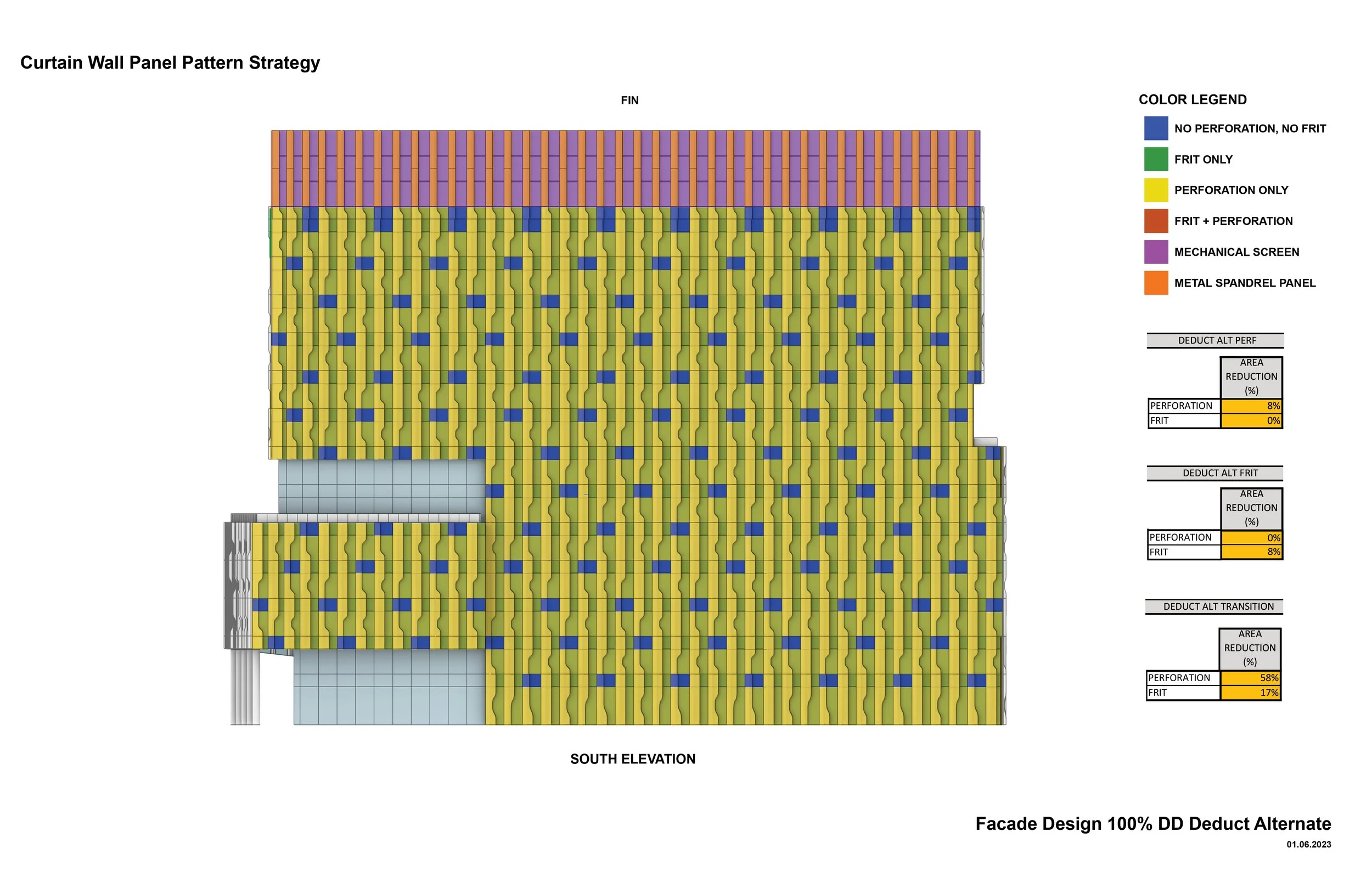
100% DD to Sub Alternate Exercise
In the end, the client selected to move forward with the more cost-effective single perforation gradient. The final design development exercise was to excise any nonessential perforation elements from the fin panels to reduce cost further. The exhibits to the right demonstrate reductions where unnecessary in the alternate perforated fin elements and frit, while also attempting to maintain the visual fidelity of the 100% Design Development scheme.
Due to how the contractor calculated pricing of perforated material and fritted glazing, only complete elimination of those elements from panels would be counted as a reduction in cost, whereas merely reducing their area would maintain the same cost.